| Overview | ||
|---|---|---|
 | Chapter 72. SPI Support |  |
Name
Overview — eCos Support for SPI, the Serial Peripheral Interface
Description
The Serial Peripheral Interface (SPI) is one of a number of serial bus technologies. It can be used to connect a processor to one or more peripheral chips, for example analog-to-digital convertors or real time clocks, using only a small number of pins and PCB tracks. The technology was originally developed by Motorola but is now also supported by other vendors.
A typical SPI system might look like this:
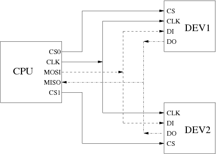
At the start of a data transfer the master cpu asserts one of the chip select signals and then generates a clock signal. During each clock tick the cpu will output one bit on its master-out-slave-in line and read one bit on the master-in-slave-out line. Each device is connected to the clock line, the two data lines, and has its own chip select. If a device's chip select is not asserted then it will ignore any incoming data and will tristate its output. If a device's chip select is asserted then during each clock tick it will read one bit of data on its input pin and output one bit on its output pin.
The net effect is that the cpu can write an arbitrary amount of data to one of the attached devices at a time, and simultaneously read the same amount of data. Some devices are inherently uni-directional. For example an LED unit would only accept data from the cpu: it will not send anything meaningful back; the cpu will still sample its input every clock tick, but this should be discarded.
A useful feature of SPI is that there is no flow control from the device back to the cpu. If the cpu tries to communicate with a device that is not currently present, for example an MMC socket which does not contain a card, then the I/O will still proceed. However the cpu will read random data. Typically software-level CRC checksums or similar techniques will be used to allow the cpu to detect this.
SPI communication is not fully standardized. Variations between devices include the following:
- Many devices involve byte transfers, where the unit of data is 8 bits. Others use larger units, up to 16 bits.
- Chip selects may be active-high or active-low. If the attached devices use a mixture of polarities then this can complicate things.
- Clock rates can vary from 128KHz to 20MHz or greater. With some devices it is necessary to interrogate the device using a slow clock, then use the obtained information to select a faster clock for subsequent transfers.
- The clock is inactive between data transfers. When inactive the clock's polarity can be high or low.
- Devices depend on the phase of the clock. Data may be sampled on either the rising edge or the falling edge of the clock.
- A device may need additional delays, for example between asserting the chip select and the first clock tick.
- Some devices involve complicated transactions: perhaps a command from cpu to device; then an initial status response from the device; a data transfer; and a final status response. From the cpu's perspective these are separate stages and it may be necessary to abort the operation after the initial status response. However the device may require that the chip select remain asserted for the whole transaction. A side effect of this is that it is not possible to do a quick transfer with another device in the middle of the transaction.
- Certain devices, for example MMC cards, depend on a clock signal after a transfer has completed and the chip select has dropped. This clock is used to finish some processing within the device.
Inside the cpu the clock and data signals are usually managed by dedicated hardware. Alternatively SPI can be implemented using bit-banging, but that approach is normally used for other serial bus technologies such as I²C. The chip selects may also be implemented by the dedicated SPI hardware, but often GPIO pins are used instead.
eCos Support for SPI
The eCos SPI support for any given platform is spread over a number of different packages:
This package,
CYGPKG_IO_SPI, exports an API for accessing devices attached to an SPI bus. This API handles issues such as locking between threads. The package does not contain any hardware-specific code, instead it will call into an SPI bus driver package.In future this package may be extended with a bit-banging implementation of an SPI bus driver. This would depend on lower-level code for manipulating the GPIO pins used for the clock, data and chip select signals, but timing and framing could be handled by generic code.
-
There will be a bus driver package for the specific SPI hardware on
the target hardware, for example
CYGPKG_DEVS_SPI_MCFxxxx_QSPI. This is responsible for the actual I/O. A bus driver may be used on many different boards, all with the same SPI bus but with different devices attached to that bus. Details of the actual devices should be supplied by other code. The generic API depends on cyg_spi_device data structures. These contain the information needed by a bus driver, for example the appropriate clock rate and the chip select to use. Usually the data structures are provided by the platform HAL since it is that package which knows about all the devices on the board.
On some development boards the SPI pins are brought out to expansion connectors, allowing end users to add extra devices. In such cases the platform HAL may not know about all the devices on the board. Data structures for the additional devices can instead be supplied by application code.
-
Some types of SPI devices may have their own driver package. For
example the
CYGPKG_DEVS_FLASH_SPI_COMMONpackage provides an abstraction layer to the standard eCos I/O Flash API package (CYGPKG_IO_FLASH) for SFDP compliant flash devices. Another common use for SPI buses is to provide MultiMediaCard (MMC/SD) support. TheCYGPKG_DEVS_DISK_MMCpackage provides a block device interface for higher-level code such as file systems. Other SPI devices such as analog-to-digital converters are much simpler and come in many varieties. There are no dedicated packages to support each such device: the chances are low that another board would use the exact same device, so there are no opportunities for code re-use. Instead the devices may be accessed directly by application code or by extra functions in the platform HAL.
Typically all appropriate packages will be loaded automatically when you configure eCos for a given target. If the application does not use any of the SPI I/O facilities, directly or indirectly, then linker garbage collection should eliminate all unnecessary code and data. All necessary initialization should happen automatically. However the exact details may depend on the target, so the platform HAL documentation should be checked for further details.
There is one important exception to this: if the SPI devices are attached to an expansion connector then the platform HAL will not know about these devices. Instead more work will have to be done by application code.
| |  | |
| Chapter 72. SPI Support |  | SPI Interface |
| 2025-10-02 | Open Publication License |